A Comparison with Currently Established Geometric Calibration Methods
A comprehensive comparison of GEOCAL based calibration with traditional checkerboard methods, demonstrating superior accuracy and efficiency across multiple camera systems.
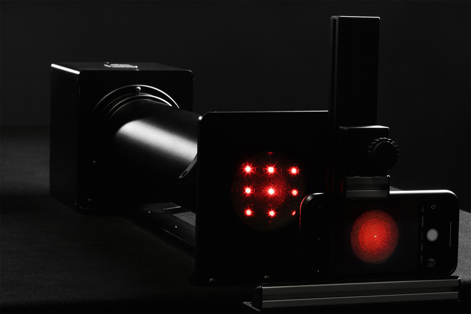
GEOCAL is a camera calibration tool that uses a combination of a LASER and a DOE (diffractive optical element) to create a grid of light spots, enabling precise geometric calibration without traditional test charts.
During the product development phase of GEOCAL, we have already involved customers who use other standard geometric calibration methods to develop their products or as a service. These methods are well-established and have been proven to work. In this paper/tech note, we will compare the results of these methods with the results of a geometric calibration performed with the GEOCAL V1.4 software. Version 1.4 is a significant step towards higher flexibility, reliability, and accuracy.
Camera 1
PhaseOne offers geometric calibration services for their cameras to customers in geospatial imaging, where extreme accuracy is non-negotiable. They provided us with a PhaseOne camera and their current calibration results for direct comparison.
The data below is the camera and the applied hardware and software.
Technical Specifications
Camera: PhaseOne iXM-RS150F-RS
Focal length: 50 mm
Pixel pitch: 3.76 µm
Sensor resolution: 14204 px × 10652 px
GEOCAL Hardware: GEOCAL XL
Software Version: V1.4.0
Applied distortion model: Even_Brown_Model
Methodology
While GEOCAL requires only a single image for calibration, we analyzed three images to ensure repeatability. The focal length was measured in pixels and converted to millimeters using the pixel pitch. Our comparison is based on the average of these three measurements.
Key Results
As PhaseOne provides undistortion function coefficients rather than distortion coefficients, we focused our comparison on focal length and principal point—the most critical parameters.
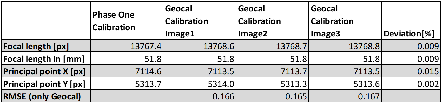
What the data shows:
The difference between both methods for focal length and principal point is remarkably small. The Root Mean Square Error (RMSE) value—representing the average offset between detected and reprojected points—is a fraction of a pixel. This demonstrates that GEOCAL's reprojected grid aligns exceptionally close to the actual detected grid, making it an important KPI (key performance indicator) for geometric calibration.
Camera 2
An automotive customer provided a golden sample camera with known reference data, presenting a different calibration challenge with its ultra-wide field of view.
Technical Specifications
Camera: Leopard Imaging
Field of View: approx. 120° (wide-angle)
Sensor resolution: 3840 px × 2160 px
GEOCAL Hardware: GEOCAL XL
Software Version: V1.4.0
Distortion Model: Custom
Variant Coefficients: 4
Key Results
We captured four images and analyzed them with GEOCAL software. The focal point and focal length showed minimal deviation from the reference data. The comparison is based on the average of all four GEOCAL measurements.

Critical Insight:
With accurate focal length and principal point data, we obtained everything needed for the intrinsic camera matrix—crucial for valid undistortion. At this development phase, the distortion coefficients were not yet directly comparable.
Camera 3: GEOCAL vs. Traditional Checkerboard
To benchmark GEOCAL against the industry-standard OpenCV Checkerboard calibration, we used our TE251 distortion chart for validation analysis.
Technical Specifications
Camera: Canon Powershot G5 X
Focal length: 9 mm
Sensor resolution: 5536px × 3693 px
GEOCAL Hardware: GEOCAL XL (SN: GC-10004)
Software Version: V1.4.1
Distortion Model: Even_Brown_Model
Validation Chart: TE251
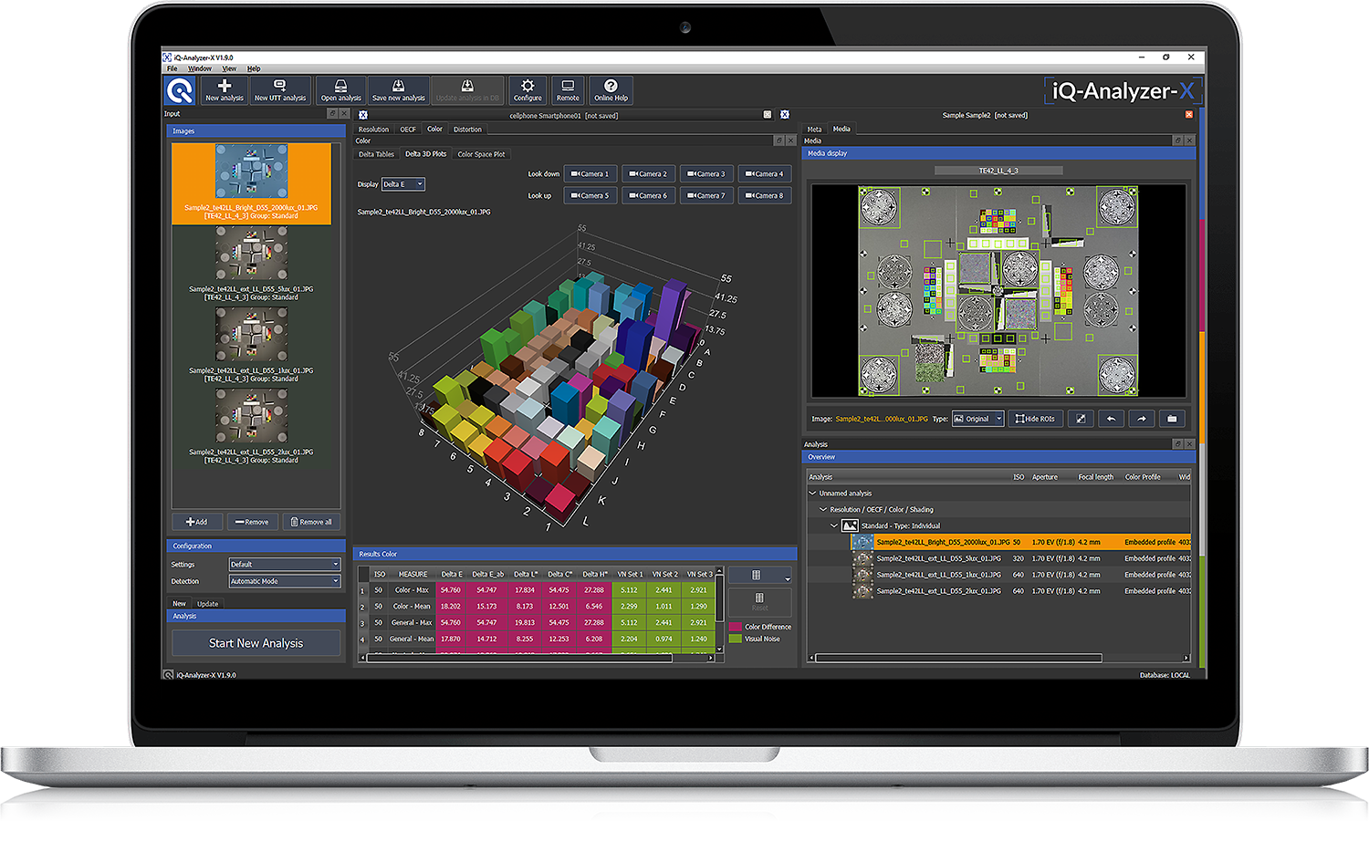
Analysis Software: iQ-Analyzer-X 1.9
GEOCAL Calibration Process
We captured the GEOCAL XL laser pattern with optimized camera settings:
- Exposure: Minimized for clear dot visibility
- ISO: Lowest setting
- Aperture: f/11
- Alignment: 0th order (brightest dot) centered, camera leveled with spirit level

The image seems to be underexposed, but this is a result of the small size of the dots, which is expected. We analyzed it with GEOCAL Software 1.4.1, applying the following configuration.
Distortion Model: Even_Brown_Model
Number of radial coefficients: 3
Number of tangential coefficients: 0 (these are more applicable in the case of a decentered or misaligned lens)
Checkerboard Calibration Process
To start the checkerboard calibration, we need at least ten images from a squared checkerboard pattern with a defined number of squares. These are the images we used:
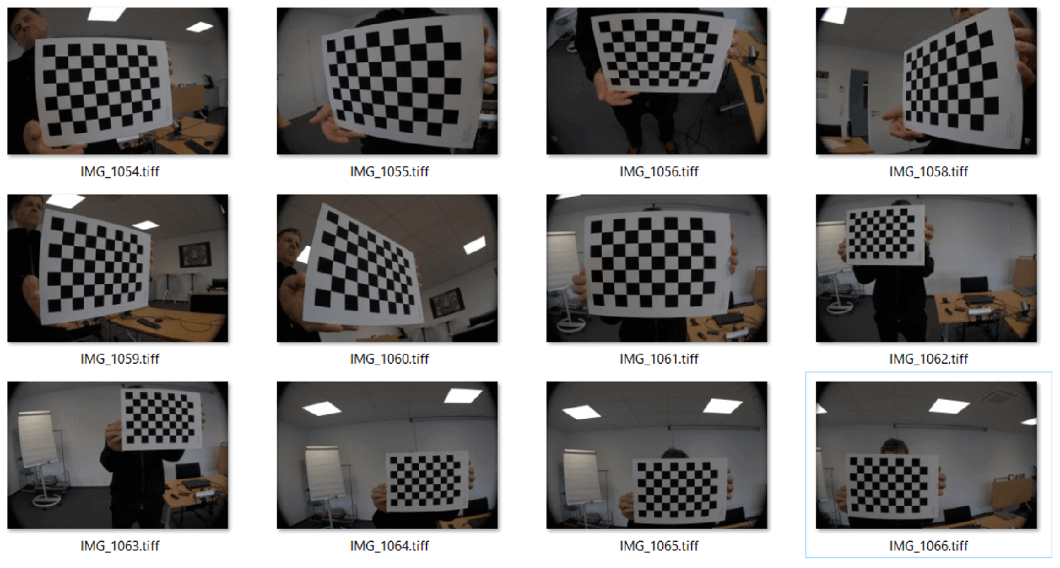
We used an example script from the OpenCV documentation for the checkerboard calibration.
OpenCV correctly detected all points. The calibration took around 5 seconds with the GEOCAL software and 95 seconds with the OpenCV code on the same PC.
After both calibrations, the intrinsic parameters and the distortion coefficients looked like this:
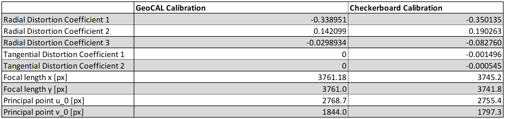
These parameters are all we need to undistort the image of the TE251. We did the undistortion with the GEOCAL and Checkerboard parameters in Python using the OpenCV undistort() function. Here is our input image:
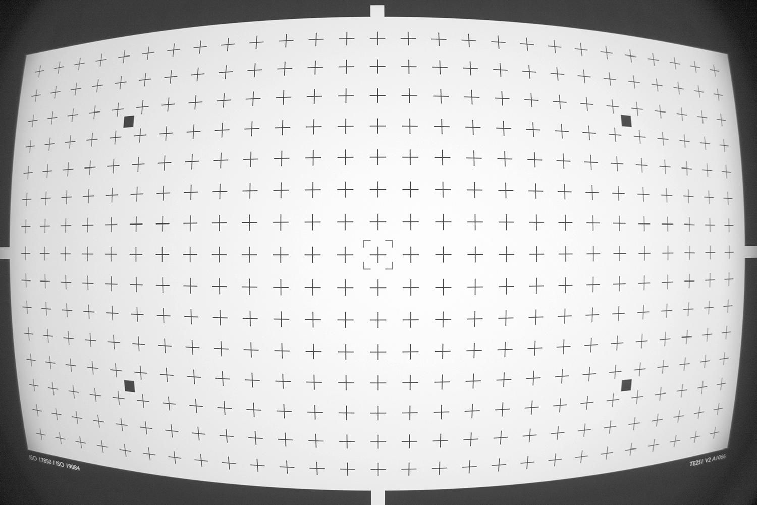
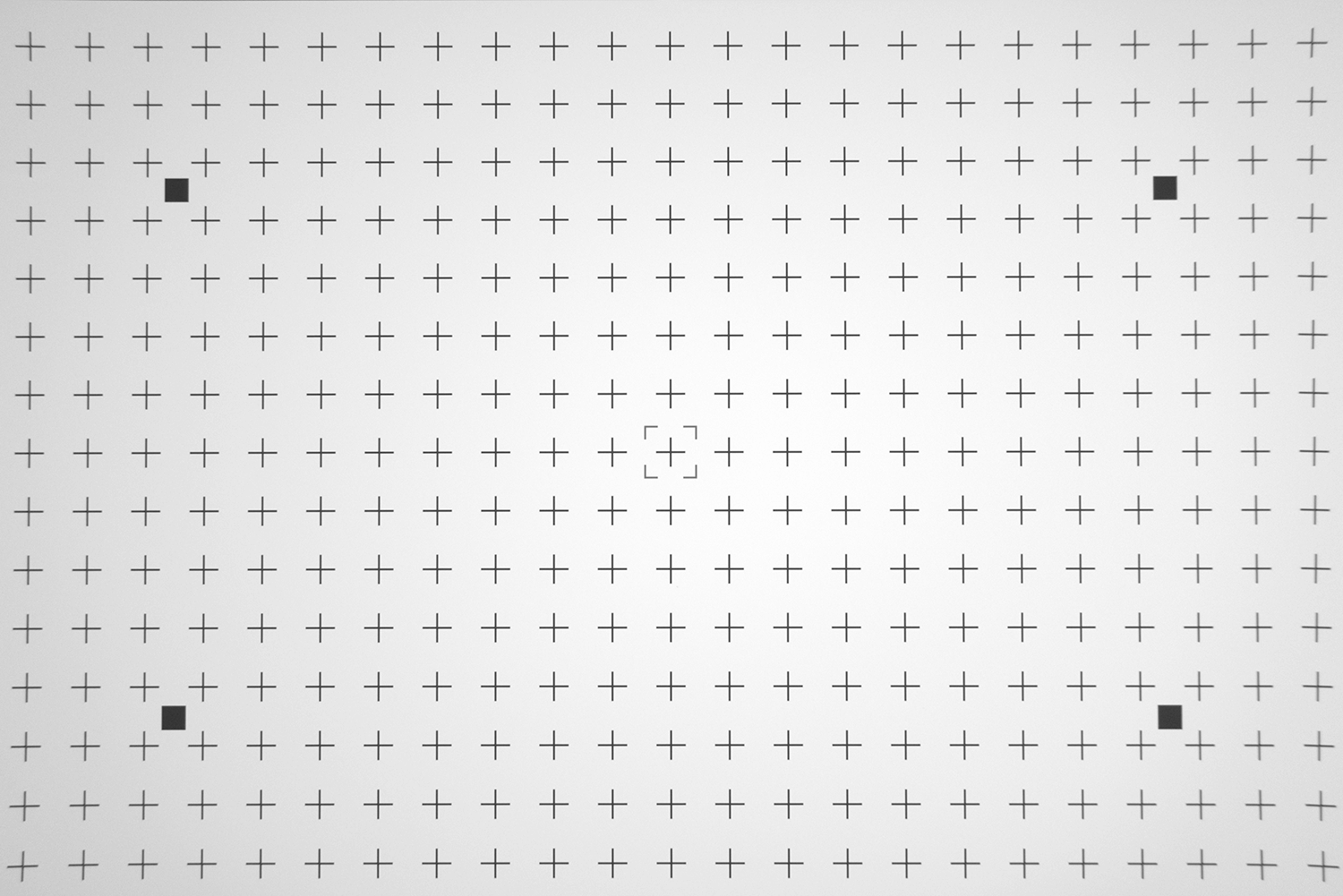
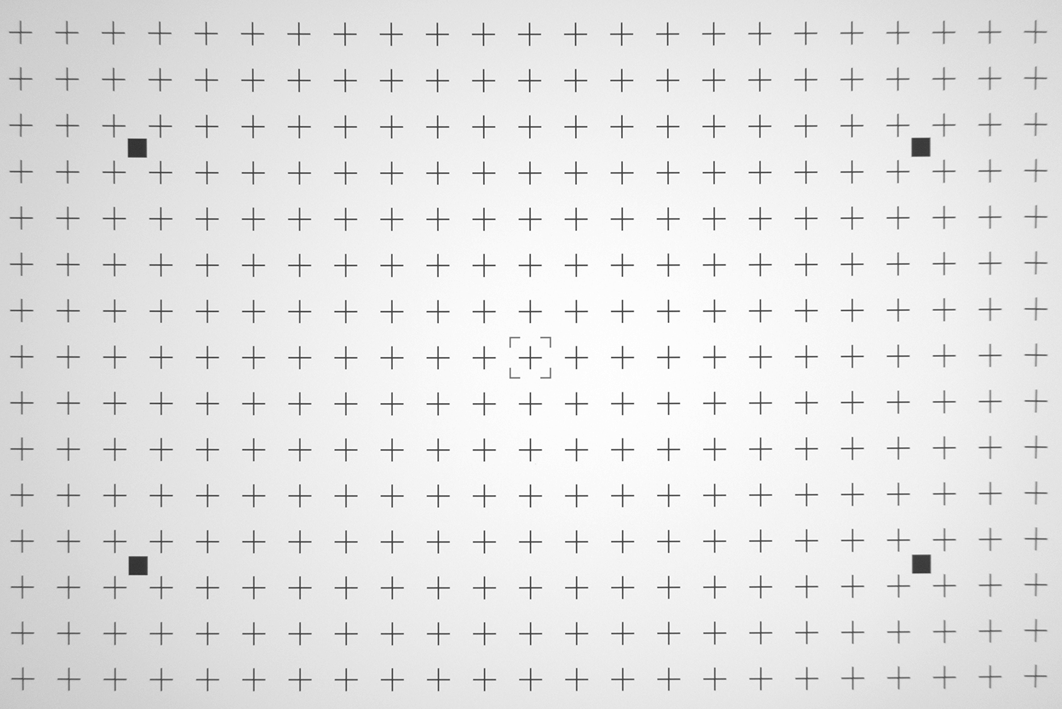
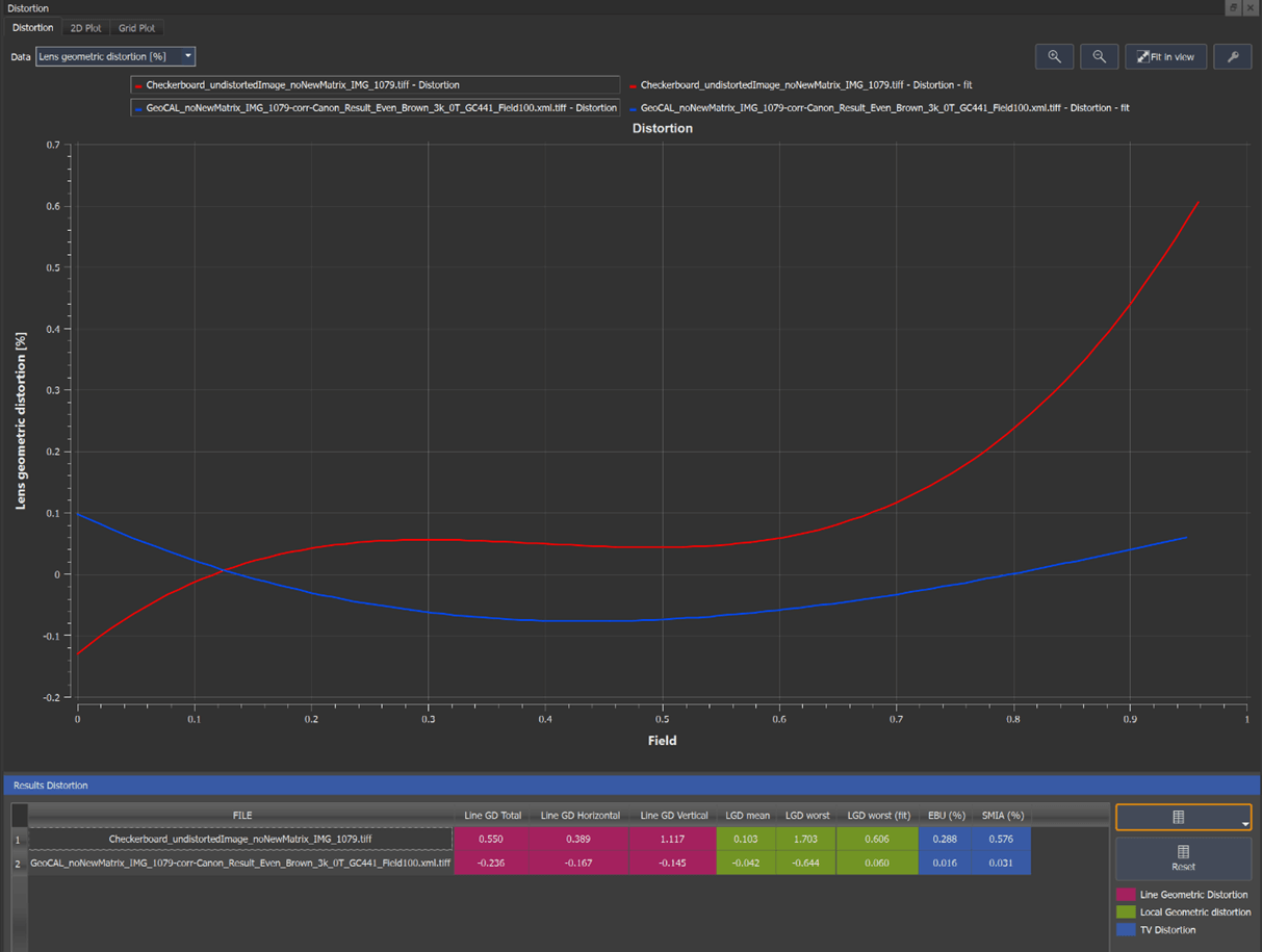
Visually slight differences are noticeable in the corners. We can get a better impression of the performance by measuring the remaining distortion in these undistorted images with iQ-Analyzer-X.
Comparative Analysis
Both methods show Local Geometric Distortion(LGD) close to zero up to 70% of the field; above 70%, the GEOCAL performs better. The lines in the plot above represent the average LGD for a specific radius/field. Imagine it is the LGD of all detected crosses in the TE251 with the same radius. To learn more about the calculation of LGD, which is a part of ISO17850, visit our website library - distortion.
The 2D plot provides a good overview of the distortion distribution over the entire image field. However, the alignment between the camera and the chart is a huge factor in the appearance of both plots.
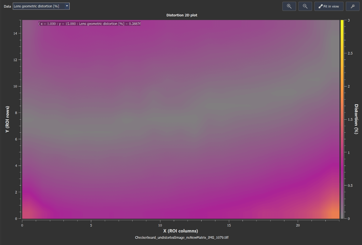
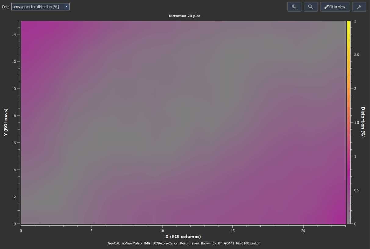
Please note that we did not use the tangential coefficients in the GEOCAL calibration, while the Checkerboard calibration does apply them. We noticed that leaving out the tangential coefficients in this case leads to better results, visually and objectively.
Key Differences:
- GEOCAL: Single image capture, faster workflow
- Checkerboard: Multiple images required, time-intensive process
- Both methods achieve comparable undistortion quality
Conclusions
Validation Success
This comprehensive comparison across three different camera systems demonstrates that GEOCAL delivers calibration accuracy comparable to established industry methods, including:
✓ PhaseOne professional calibration services
✓ Automotive golden sample references
✓ Traditional OpenCV checkerboard methods
Key Advantages
Single-shot calibration: Unlike checkerboard methods requiring 15-20 images, GEOCAL achieves precise results from just one capture
Consistent accuracy: RMSE values consistently below one pixel across all test scenarios
Versatile application: Successfully validated on cameras ranging from professional medium-format to consumer compact and automotive wide-angle systems
Future Outlook
GEOCAL V1.4 represents a significant leap forward in geometric calibration technology, combining the accuracy of traditional methods with unprecedented workflow efficiency. As we continue development, we're committed to pushing the boundaries of calibration precision and ease of use.
Why Geometric Calibration Matters
GEOCAL is a revolutionary camera calibration tool that uses advanced laser technology to project a precise grid of light spots, enabling accurate geometric calibration without traditional test charts. This technology enhances camera accuracy across critical industries like automotive, security, and geospatial imaging